400 Coaxial Cable 500 ft. Reel (50 Ohm, Amphenol Times Microwave)
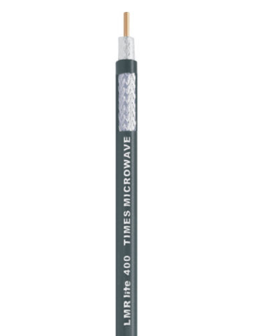
400 Coaxial Cable 500 ft. Reel (50 Ohm, Amphenol Times Microwave)
Buy Now, Pay Later with No Interest if paid in full within 6-12 months. Choose Klarna payment option at the checkout for details of this, and other long-term low-interest financing options.
Free Lifetime Support. SKU / Model: LMR-400
1(855)846-2654
Need installation quote, or help with designing a custom solution? Submit a request for quote.
- Description
- Reviews
- Questions & Answers
- Make An Offer
- Warning
Description
Product Description
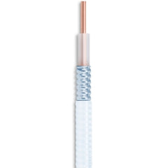
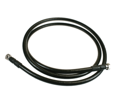
Made in USA, this 400 coax cable 500 feet reel length has 50 Ohm impedance. It is manufactured by Amphenol Times Microwave. It can be used as a drop-in replacement for RG-8/9913 Air-Dielectric type cable. It offers very low loss communication over coax. It is an ideal choice for jumper assemblies in wireless communications systems. Must be used for short antenna feeder runs because it is not recommended for over 100 ft. runs. Otherwise, it is suitable for practically any application such as WLL, GPS, WLAN, WISP, WiMax, SCADA, and mobile antennas that need an easily routed, low loss RF cable.
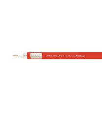
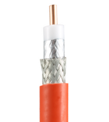
The Times Microwave 400 type cable's a low loss braided coaxial cable. This 3/8 inch 50 Ohm coaxial cable has a stranded outer conductor and a bare copper center conductor. A 100 percent foil and 88 percent coverage braided shield prevents loss. It offers similar performance compared to corrugated copper cables but provides higher flexibility (1 in bending radius) and simplified connection. It can be used in almost any application where handling characteristics, improved shielding, and low loss is required.
Specifications Overview:
| Part Number | 400 |
|---|---|
| Application | Outdoor |
| Jacket | PE |
| Jacket Color | Black |
| Impedance (Ohm) | 50 |
| Center Conductor Material | Copper Clad Aluminum |
| Loss @ 50 MHz | 0.90 dB |
| Loss @ 100 MHz | 1.2 dB |
| Loss @ 400 MHz | 2.5 dB |
| Loss @ 900 MHz | 3.9 dB |
| Loss @ 1000 MHz | 4.10 dB |
| Shield % | 100% foil 88% braided |
| Center Conductor Diameter | 0.108 in. |
| Nominal O.D. | 0.405 in. |
| Center Conductor Construction | Solid |
| VOP | 85 % |
| Dielectric Insulation | PE |
| Manufacturer | Times Microwave Systems |
| Nominal Core O.D. | 0.285 in. |
| Nominal Capacitance (pF/ft) | 23.9 |
Construction Materials:
| Inner Conductor | Solid BCCAI, 0.108 inch |
|---|---|
| Dielectric Material | Foam PE, 0.285 inch |
| Outer Conductor | Aluminum Tape, 0.291 inch |
| Overall Braid | Tinned Copper, 0.320 inch |
| Jacket Color | Black |
Electrical Specifications:
| Velocity of Propagation | 84% |
|---|---|
| Dielectric Constant | 1.38 |
| Time Delay | 1.20 nS/ft (nS/m) |
| Impedance | 50 Ohm |
| Capacitance | 23.9 pF/ft (pF/m) |
| Inductance | 0.060 uH/ft (uH/m) |
| Shielding Effectiveness | >90 dB |
DC Resistance:
| Inner Conductor | 4.6 ohms/1000ft (/km)/td> |
|---|---|
| Outer Conductor | 5.4 ohms/1000ft (/km) |
| Voltage Withstand | 2500 Volts DC |
| Jacket Spark | 8000 Volts RMS |
| Peak Power | 16 kW |
Mechanical Specifications:
| Bend Radius: installation | 1 in. (mm) |
|---|---|
| Bend Radius: repeated | 4 in. (mm) |
| Bending Moment | 0.5 ft-lb (N-m) |
| Weight | 0.068 lb/ft (kg/m) |
| Tensile Strength | 160 lb (kg) |
| Flat Plate Crush | 40 lb/in. (kg/mm) |
Reviews
Questions & Answers
QUESTIONS & ANSWERS
Have a Question?
Be the first to ask a question about this.
Data Sheet / User Guide
Make An Offer
Warning
Note: For any signal booster to help, outside signal strength must be at least -110 dB or there must be a clear line of sight to a cell tower that is within twenty miles. Before ordering, please check outside signal level in decibels or ensure that you can make and hold a phone call at any good spot outside where you can mount an exterior antenna. Square footage stated in signal booster listings is based on good signal outside. If it is any weaker, the boosted sq. ft. area will be considerably lower, accordingly.
Kevin K. of Anderson, California gave the following review:
Website is easy to use with plain straight forward info but could have had more on testing signal strength to make sure you get a strong enough booster.
Therefore, please note that stated sq. ft. coverage is based on good signal outside. For best results: If outside signal is weak, we suggest choosing the next higher sq. ft. coverage kit. If outside signal is very weak, we suggest choosing the kit with even more higher sq. ft. range bracket. Basically, higher the sq. ft. bracket, the more powerful the signal amplifier with greater Gain as well as higher uplink and downlink output power.
If outside signal is too weak (weaker than -110 dB), submit request for cell coverage solution assessment. Upon receipt of questionnaire, we will perform residential or business site survey. This will help us determine the system that is needed to improve cell coverage. Then, we will create system design using that system such as femtocell, active or hybrid distributed antenna system (DAS), or other carrier feed signal enhancing method available that will work at your signal-challenged location. Finally, we will schedule for installation after equipment and installation service quote has been approved by you, or your company.
For non installation-included kits: Most home / office / building cell signal booster kits only include bracket to mount exterior antenna on outside wall, edge of roof, or existing pipe up to 2 inches in diameter. Mounting pole not included with most kits, unless stated specifically that it is included for free. Therefore, a mounting post must be purchased separately if you will require it to mount exterior antenna.

Related Products


